Programming the XRP robot
Brad Miller
Welcome to Introduction to Robotics
Welcome to the WPI Global STEM Education Initiative Introduction to Robotics class using the new XRP Robots. This class is intended to be used by instructors to learn about the basics of robotics and programming using either Blockly or Python. The course is designed to use the Python language. Or you may start with Blockly and switch to Python as you gain more familiarity with programming the robots.
The class has several modules you can work through, starting with an introduction to robotics. Modules include driving, using sensors, and using the manipulator (robot arm). Finally, there is a challenging final project that brings together everything you have learned in the previous modules. The final challenge optionally has a rubric for scoring the runs completed by your students by adding some competitiveness to the class if you would like to use that.

We hope that you find this course fun and engaging for you and your students. This is a brand-new course with new robots and software, so there may be bugs and unexpected problems. We will strive to be responsive to any questions you might have. If you have any questions or find anything not working as you expect it to, feel free to contact us.
For additional information about the program, please see the XRP web page.
Course Overview
This course is designed to teach the knowledge and skills necessary for a basic understanding of programming for your XRP robot using either the Python or Blockly programming languages. The intent of this course is that it is interactive, and we expect you will work on every intermediate challenge. At the end there is a final project challenge requiring all the skills that are taught in the modules leading up to it. Each module builds on the previous by adding new robotics and programming concepts. New programming techniques are introduced to solve concrete robot problems, not as abstract unattached learning. This way students will see the relevance and need for each concept introduced.
The modules are outlined in the syllabus along with the learning objectives associated with each one. There are also short quizzes throughout the course to help students make sure they are learning the important concepts.
The course can be run with one robot per student or with teams of a few students working on each robot. Working in teams allows students to help each other as they work through the course. But one student must not be doing all the work, preventing the other team members from learning the material.
Joining Course Platforms
Alongside this Canvas course, you will be using several online resources for getting your questions answered. The support tools for any technical Q&A will be monitored by the development team and a growing community of users like you. We are using Canvas Discussions and Discord for online support during this course.
Discord
The Global STEM Initiative Discord channel provides an easy way to communicate your questions, concerns, ideas, and conversations across the world (within this robotics program). Technical questions can be asked here, but it is strongly advised to ask them in Canvas Discussions so others can find the answers in the future. You may find important resources, links, event information, and office hours here.
Please follow these steps, or follow the video below, to join the Discord Channel:
- You will want to create your account, go to https://discord.com/ Links to an external site..
- On the top right of the screen, click on the login button, and at the new screen on the bottom, it will say "Need an account?" press the register button highlighted in blue next to this text.
- Input all the information to the new screen, and press continue.
- Now you should have a new screen that says "Create your first Discord server" at the top. At the bottom, in blue text, it will ask you if you have an invite already. Click the blue text, and give the prompt this link: https://discord.gg/fAE2YhVM4HLinks to an external site.
- Finally, you should verify your email with a link that Discord has sent you to the email you provided them.
- And you are done! You can now ask any questions you have about the course here or just chat with the other members of the course. We hope you will find this course fun and interesting!
If you want Discord on your phone, for Android or iPhone there should be a Discord app in the App Store that you can download. You can also download a desktop app for Discord, the link can be found on the website in step 1.
If you have any problems following the above steps, here is a step-by-step video to join our Discord Channel.
https://www.youtube.com/watch?v=0nXCPWrGXwwLinks to an external site.
Contact Us
If you have any trouble following any of the above steps, please reach out to the Course Staff via Canvas or Discord.
Or email your questions and concerns to gr-globalsteminitiative@wpi.edu
Introduction Overview
Overview
Topic Description
In this module you will:
- Learn about the field of robotics
- Assemble your robot
- Install the software required for programming the robot
- Write a short program to familiarize themselves with programming the XRP robot.
At the end of this module, you will be able to:
- Recognize the characteristics of robots
- Talk about the core disciplines that make up the field of robotics
- Understand the components of the robot and how it is assembled
- Have familiarity with the tools for programming
To finish this module, review and complete all tasks outlined in each section. Then successfully pass the module quiz at the end.
What is a robot
In this course we talk about robots as devices that can:
- Sense their environment
- Think and perceive what is happening around the robot
- Carry out actions using actuators (motors)
There are many ways to define a robot, and this is only one of them. Still, it is a good idea to have a definition of precisely what a robot is. Let's look at different devices and try to decide whether each of these are robots according to our definitions.
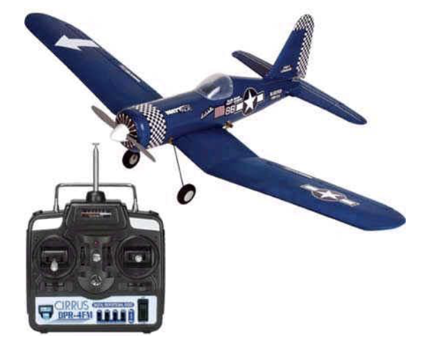
Radio controlled airplane
A radio-controlled airplane is operated by a person who holds a controller and uses the joysticks to control the airplane's flight path. It requires a remote pilot.
Actuators:
- propeller motor
- three control surface motors
Sensors: NoneSummary: No sensors, no thinking, and it has to be controlled entirely by a human.
Not a robot.
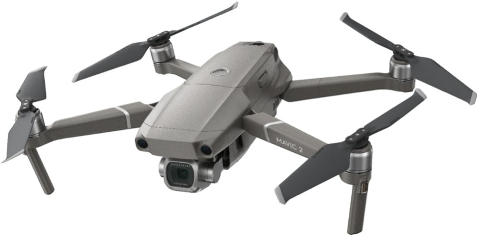
Drone
A quadrotor drone is capable of being teleoperated or using autonomous flight. The drone can fly a programmed course, avoid obstacles, return to the landing point, and automatically land.
Actuators:
- Four propeller motors
- camera aiming motor
- Sensors:
- GPS (Global Positioning System) receiver
- gyros and accelerometers
- heading sensor
- altitude sensor
- rangefinder
The drone senses the environment based on its sensed location and surroundings and flies on its own from one place to another.
This is a robot.
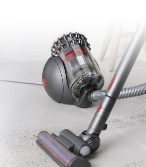
Conventional vacuum cleaner
A conventional vacuum cleaner is pushed by an operator around the area to clean the floor. Actuators: Motor to turn the fan that sucks up dirt.
Sensors: Fan speed sensor to ensure consistent performance. The motor does have a sensor that keeps the motor running at a predetermined speed, but it does not sense the environment or have perception. The operator must supply all the "smarts."
Not a robot.
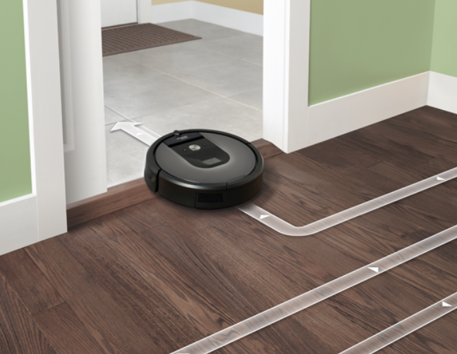
Autonomous vacuum cleaner
An autonomous vacuum cleaner can — on its own — start up, vacuum one or more rooms, come back to clean its home base, then continue vacuuming until the whole job is done. It maps out each room in the house for more consistent operation.
Actuators:
- Drive motor for the wheels to get around.
- Motor for the vacuum for cleaning.
- Motor in the base (not shown) that will suck the dirt out of the vacuum cleaner so it can continue cleaning.
Sensors:
- Camera for visualizing the room.
- Switches on the bumper to allow it to turn around after hitting obstacles.
- Rangefinders on the side to measure distance from walls.
- Sensor to detect carpet vs. floor to change the motor speed.
An autonomous vacuum is pretty smart. It can learn the map of a house after a few runs and efficiently clean rooms. It can avoid obstacles, clean rooms, stop to recharge, and continue where it left off.
This is a robot.

Self-driving car
A self-driving car can be driven conventionally by a human or driven autonomously on city streets and highways on its own.
Actuators:
- Wheels for driving.
- Motors for controlling turning.
- Actuators to allow the robot to brake on its own.
Sensors:
- 8 cameras both outside and inside the car to view the environment and driver's attentiveness
- Rangefinders all around the car to measure the distance to adjacent vehicles
- GPS to determine the car's location, and more.
The car is smart and represents state-of-the-art robotics. It can sense the environment, understand where it will be over time, and drive to its destination while safely avoiding obstacles.
This is a robot.
What are the parts of robotics?
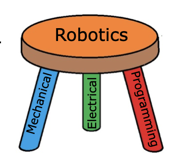
Robotics engineering is usually thought of as a combination of three disciplines. They are:
Mechanical engineering - the design and analysis of mechanisms and other mechanical systems.
Electrical engineering - the design of electronic circuits, especially all the sensors.
Computer science - developing advanced software (computer programs) to interpret all the sensor data, understand it and drive the actuators.
Robotics can be thought of as the synergy of these three fields. Designing robots requires a "systems" approach to design. Knowing all three subjects allows one to develop more complex and capable systems than one with only a unitary background.
Building the XRP robot
Building the XRP robot
The attached PDF file contains preliminary assembly instructions for the beta XRP Robot kit distributed at the FIRST Global competition in Geneva.

Installing the programming tools
We will focus on two primary programming tools for this course:
Blockly
This is a drag-and-drop graphical programming system similar to Scratch. Blockly is a good choice for getting started programming the robot, especially for learners with little to no programming experience. Graphical programming like this does not easily scale to larger programs and is only usable within the Blockly programming environment.
Python
A more widely-used language that scales well for larger programs and works with professional programming tools such as Visual Studio Code and many others. The tool that will be used throughout this course for python programming is Mu editor although a more professional tool such as Visual Studio Code can also be used for writing CircuitPython code that is used by the XPR Robot.
Note: A way to get students comfortable with programming more quickly is to start with Blockly getting through basic concepts such as functions, conditionals, loops, and all the basic robot operations. Then move to Python to complete the course, especially for some of the more complex challenges, such as the final project. This will allow quick onboarding without having to learn too many new concepts simultaneously. But the decision will depend on the lever and experience of the students taking the course.
Installing Mu Editor
Mu is a simple and concise editor that allows us to edit our CircuitPython code and view serial output from our robot. To install, go to the following webpage: https://codewith.mu/en/download

Download the file corresponding to your operating system, and then open the downloaded file and follow the installation prompts provided.
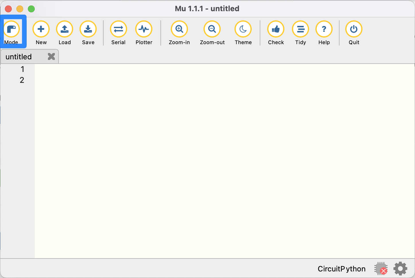
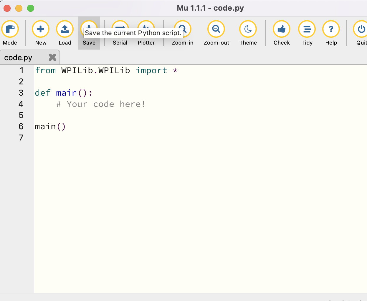
Mu allows you to run different implementations of Python for different microcontrollers. In our case, we want to run CircuitPython, which is compatible with our Maker Pi RP2040. Select the “Mode” button shown below.
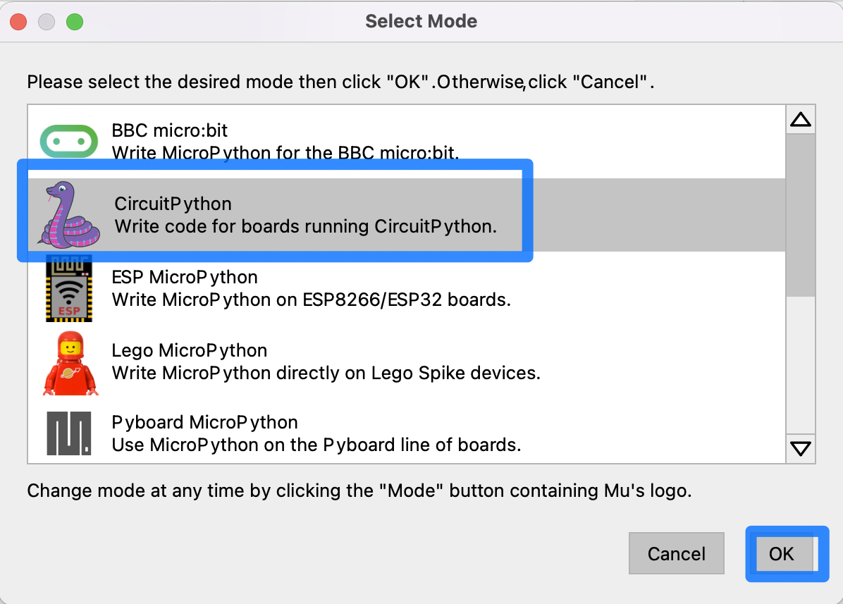
Select CircuitPython and confirm by clicking ‘OK.’
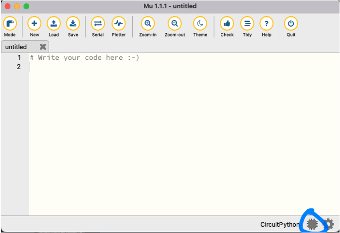
In the Mu Editor, you may notice a symbol of a red ‘x’ on a microchip in the bottom right corner of the window.
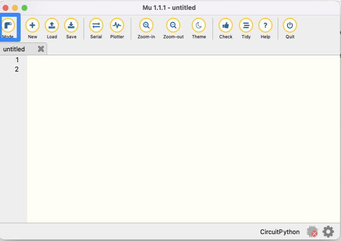
This indicates that Mu has not detected a robot device attached to the computer. In order to write and download programs to the robot, you’ll need to connect your computer to the robot via a Micro-USB cable. Connect the robot and turn it on using the switch near the back of the robot chassis.
Some micro USB cables are only designed to carry power. The one provided in your kit will carry power and data which is required for programming your robot.
At the bottom right corner of the screen, the red "chip" icon will now be grey, indicating a successful connection between the robot and the computer running Mu Editor.
At this point, you can upload and run programs to the robot written in the main window.
Additional resources about using Mu Editor for programming your robot can be found on the project website: https://codewith.mu
Installing the software libraries on your robot
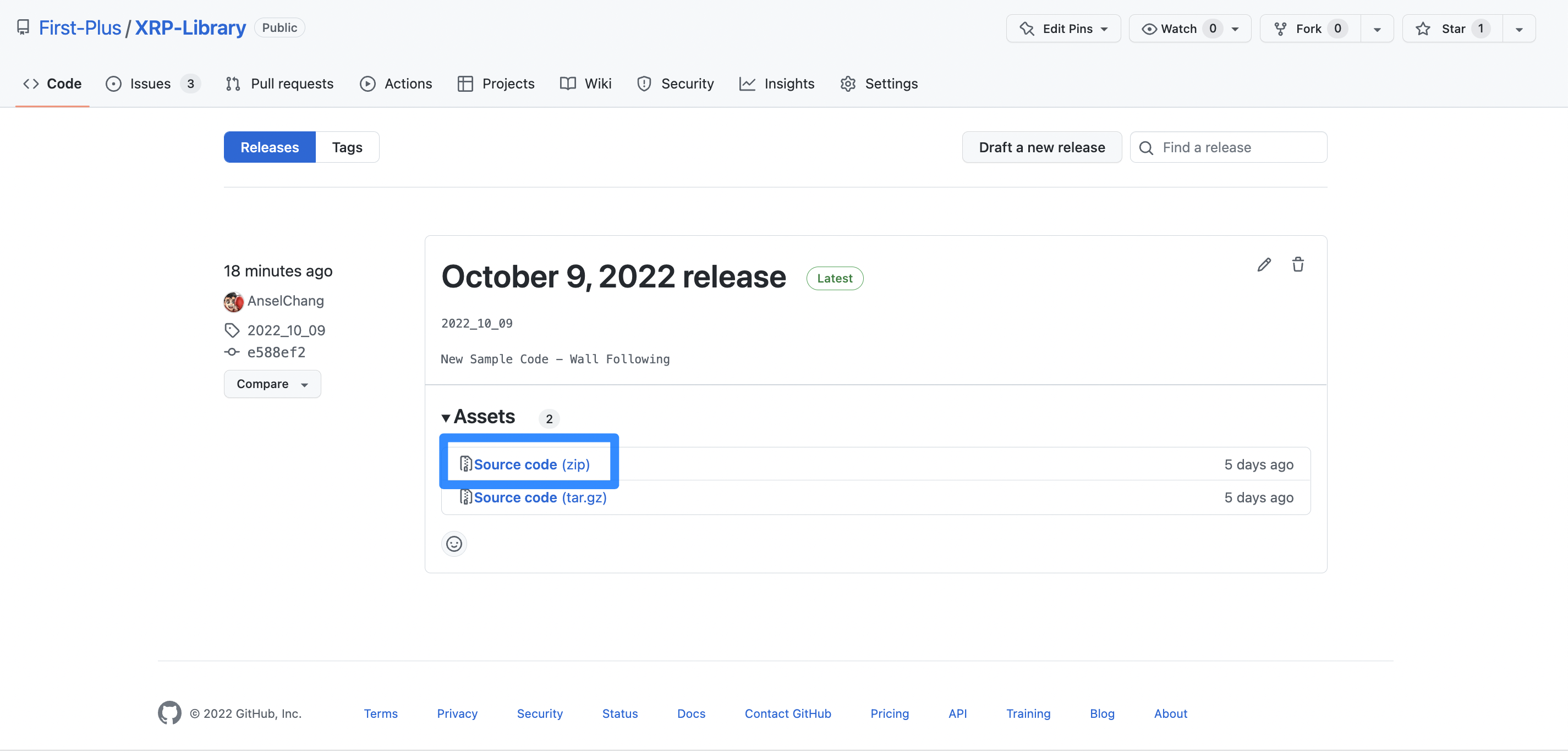
The software library makes it easy to write programs to control the robot and will be used throughout the course. To install it, go to https://github.com/GlobalSTEMEdInitiative/XRP-Library/releases and download the "Source code" (zip) file.
Then, unzip the folder. To do this, open Finder on Mac, or File Explorer on Windows. Go to your Downloads folder and find the zip file. On macs, double-click the zip file to unzip it, and on windows, right-click the zip file, and click "Extract All..."
Next, look for an external drive labeled ‘CIRCUITPY’. If the robot is correctly connected to the computer and turned on, this folder should be visible in Finder/Windows Explorer.
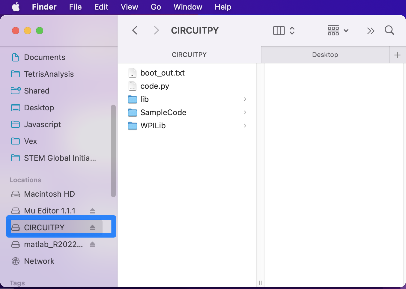
This is where programs can be edited and run. Delete anything that is currently in the drive. Then, go inside the unzipped folder and copy the contents of the folder into the CIRCUITPY drive. The robot should now be set up with the library!
Writing your first robot program: Python
As mentioned earlier, we'll be using Mu to edit and run CircuitPython code and view serial output from the robot. To start, open up the Mu application.
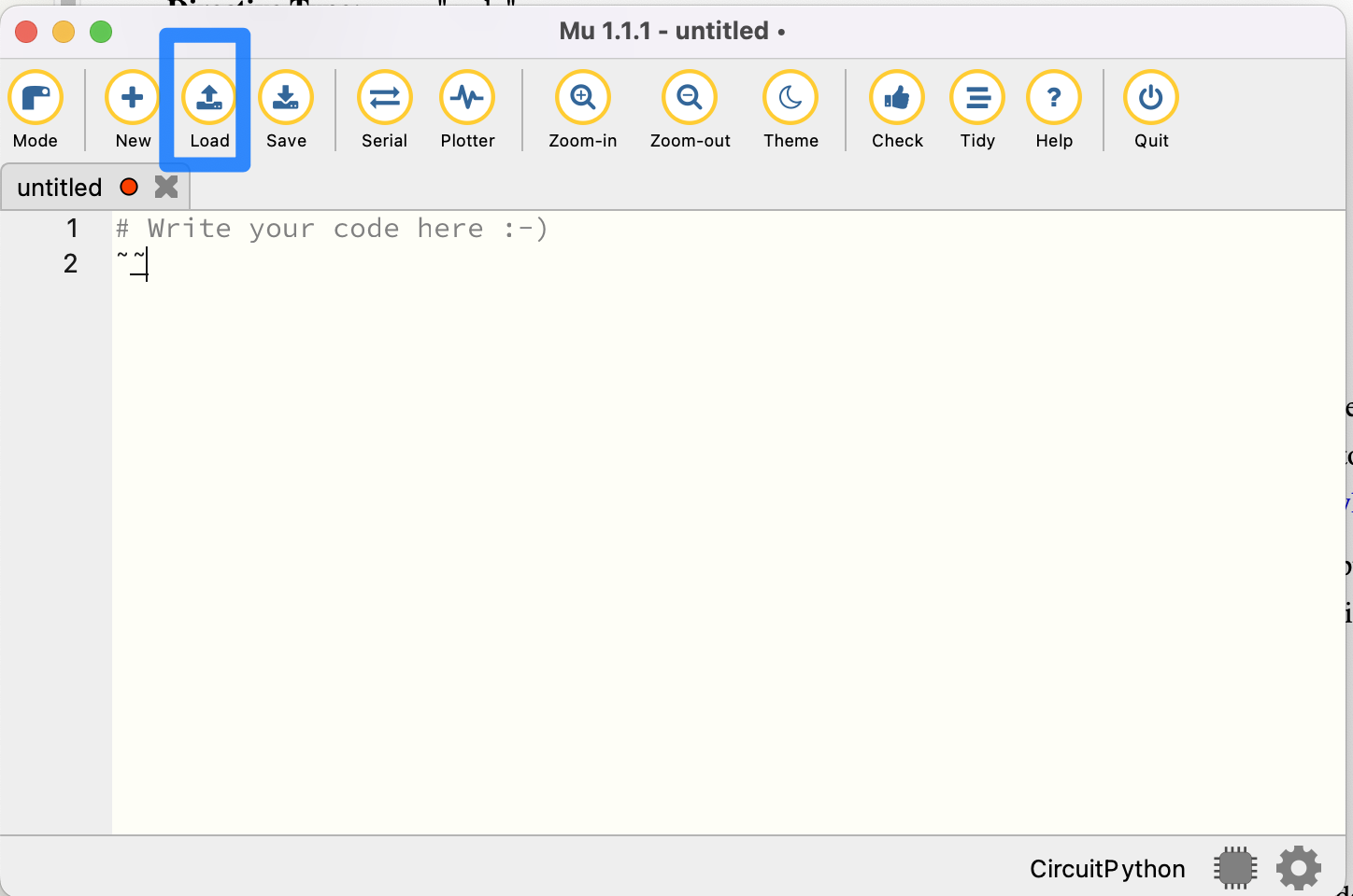
Then, click the “Load” button as shown above. Navigate to the CIRCUITPY drive and open code.py.
code.py is the file that contains the robot code. In order to run a program, simply edit code.py, save your changes, and your program will automatically start executing on the robot!
Before we write any code, though, there's a neat feature that will prove quite helpful when testing your programs.
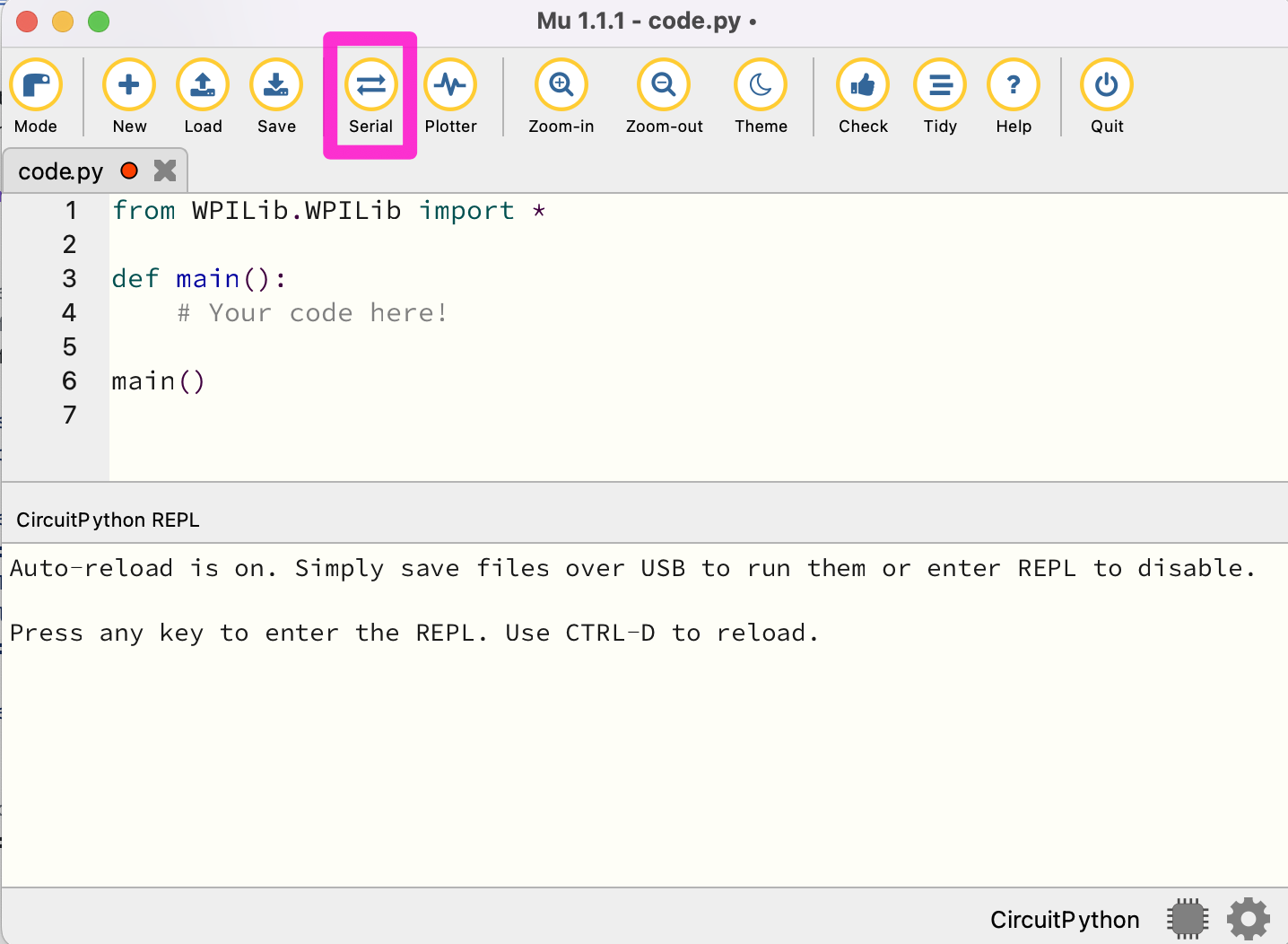
Click the ‘Serial’ button. If the robot is connected to the computer, this will allow you to view your robot’s logs on your computer while running your program, which is very useful for debugging.
Python Programming Notes
Note 1: This course is a hands-on learn-as-you-go course. We will not be teaching you how to program in Python. But if you follow the patterns presented, you should be able to fill in the blanks and accomplish the tasks. If you want to learn more about Python, we suggest looking at https://www.w3schools.com/python/default.asp Links to an external site. as a resource.
Note 2: The Mu program is designed to save the current program to your robot for execution. If you would like to save a program for future use, we suggest that you copy and paste it into an editor program, such as notepad, on your computer for future reference. We also suggest saving a copy of the current program in the editor as a base for each new program or challenge you start.
Note 3: With Python, the amount of indentation of a line of code is important. For instance, in the program below, all the indented lines are part of the main program. We suggest using the 'tab' key for indenting so that all the code is indented the same amount.
Note 4: Any line that starts with a # character is a comment. Comments are not executed as part of the program. They are notes to help you remember what you were doing in that part of the program.
Finally, let’s test some code out. Often, it's a tradition when learning a new programming language for the first program to display "Hello World!". Let's put our twist on this tradition with our robot. Add the following code to code.py:
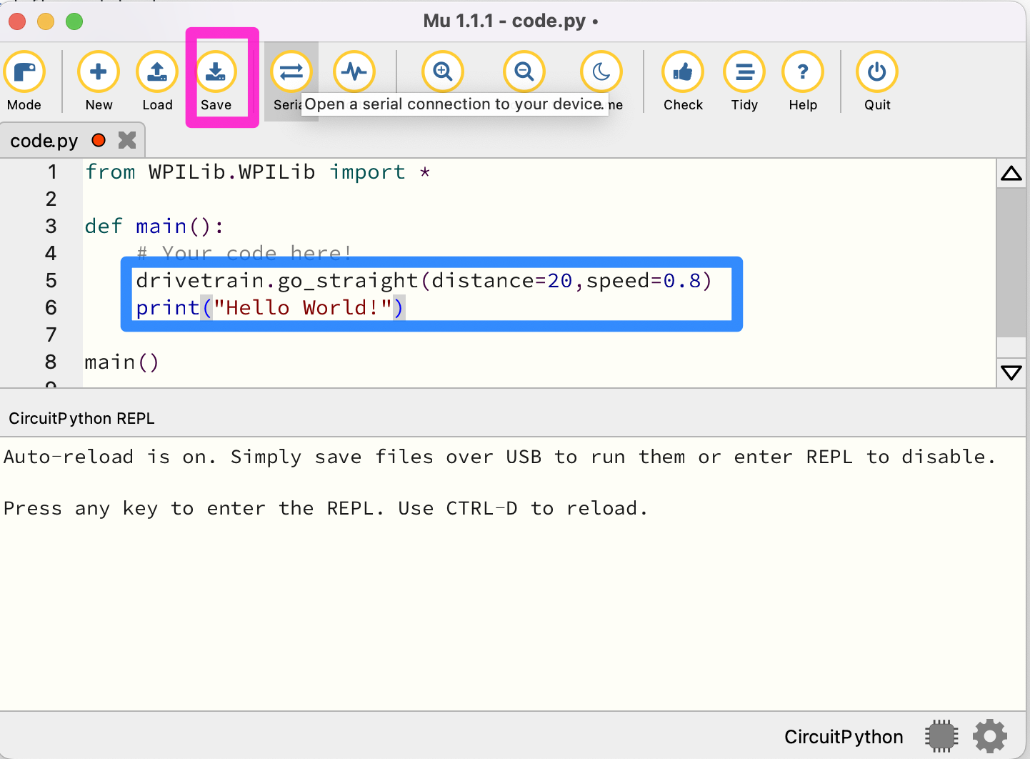
Then, click the ‘Save’ button. CAUTION: As soon as you hit save, your robot will start moving. Remember, saving your changes causes the robot to initiate running the program automatically! Note that pressing Control-D will also start running your code.
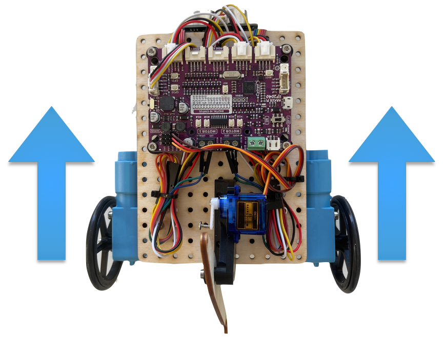
You should see the robot immediately start going forward for 20 centimeters. Then, it should log “Hello World” on your computer through serial output. If nothing goes wrong, you have successfully set up the software and are ready to write more intricate code!
Robot Driving Overview
In this module, you will:
- Learn how to set the power to the robot's drivetrain
- Understand the relationship between the motor efforts and the robot's motion
- Be introduced to motor encoders and how to use them to correct the robot's motion
- Use the pre-made drive, turn, and button functions
At the end of this module, students will be able to...
- Control the robot's basic motions
- Understand the basics of while loops and exit conditions
- Have familiarity with making and running functions
- Break down a larger path into components and then convert them into code
To finish this module, review and complete all tasks outlined in each section. Then, successfully pass the module quiz at the end.
Effort vs. Speed
Getting the Robot to move
Getting your XRP robot to move is pretty easy. On a basic level, all movement commands boil down to this one method:
drivetrain.set_effort(left_effort: float, right_effort: float);
A method is a grouping of code for a common purpose. For example, the drivetrain.set_effort function sets the drivetrain to move at the effort values you, as the programmer, specify. These input values into the method are called parameters and are essential for giving methods context that may change at various points.
So what is an effort value?
An effort value is a measure of how much voltage is sent to the motors. Sending more voltage to the motors results in it running at a higher speed or it producing more torque or both.
In our case, effort values must be between -1.0 (full power in reverse) and +1.0 (full power forwards), with 0 being off. Any thoughts on what 1/2 effort would be?
Let's test this so we can get a better idea of what effort values mean:
In code.py, inside def main():, add the following line of code to run the motors at full power. This is where you will be putting most of your code moving forward.
Python Programing Notes:
Note 1: The while loop will continue to loop through the statements that are indented underneath it until the while condition is no longer true. The while True: will continue to execute forever, also known as an infinite loop.
Note 2: time.sleep(0.1) tells the program to do nothing for 0.1 seconds.
Note 3: It is good practice to put the robot up on a stand like a roll of tape so the wheels can run free without hitting the table. This keeps the robot from running off the end of the table. When a program in an infinite loop like this is started, it will keep spinning the wheels until the program is changed. To stop the wheels from turning, you will need to delete or comment out the drivetrain.set_effort(1.0, 1.0) line and save the program again.
def main(): while True: drivetrain.set_effort(1.0, 1.0) time.sleep(0.1)
Notice that the effort values used above are 1.0, which represents half effort forward. What would you use for half effort forward and half effort backward?
Then, upload your code to the robot and let the robot drive on a flat surface. Record how fast it goes. Try measuring how fast it travels in a few seconds!
Afterward, place the robot on a ramp and run it again. Take notice of how the robot moves slower when on the ramp. Why does this happen?
Mini-Challenge: Climbing Slopes
So if a robot drives slower up a ramp, the natural question would be: how steep of a slope can the robot climb?
Have your robot drive on a ramp and then raise the ramp until the robot is no longer able to move forwards. Is that angle what you expected? If your robot started sliding back down the ramp, think about why that happened.
Differential steering
In the last section, we learned how to set the motor efforts. But currently, you only know how to get the robot to go straight! Let's fix that:
Since there is no steering wheel like you would find on a car, the way to control the robot is by varying the wheel speeds relative to each other. This is called differential steering because the difference in wheel speeds controls the direction of the robot. As we go through each type of motion, give it a try on your robot to get a better grasp of what is happening!
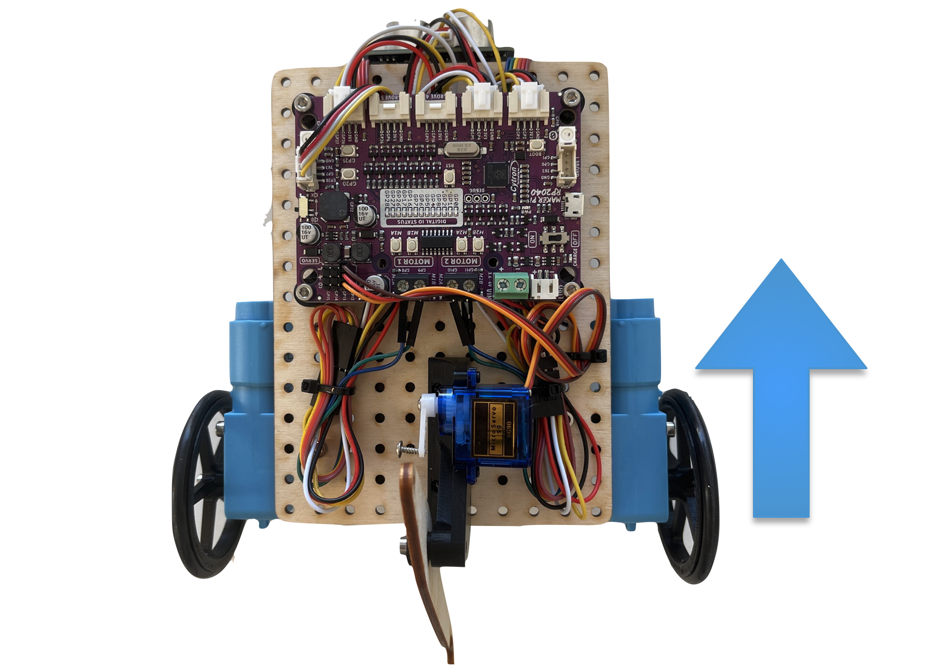
Driving straight
As you saw in the previous section, when the left wheels and the right wheels are moving forward at the same speed, the robot will drive in a straight line. This is illustrated in the following image where the length and direction of the arrows shows the wheel speeds:
- Both arrows going forward means the wheels are turning in a direction that causes the robot to move forward and
- The length of the arrows being equal indicates the wheels are each going at the same speed.
Try setting the motor efforts to be equal to each other to confirm the robot drives straight.
Note: The robot turning a tiny bit while trying to drive straight is normal. We'll address how to fix this in the next section.
Turning
When turning, there are a variety of paths that the robot might follow, whether that be a gentle curving turn to a turn in place. All of these variations can be achieved by changing the difference between the motor efforts. Let's take a look at the main categories of turns:
Making a sweeping turn right or left
If the left wheel turns faster than the right wheel, the left side of the robot tries to get ahead of the right side, resulting in a right turn. Similarly, if the right wheel turns faster than the left, the robot turns to the left. Try setting your motor effort to two non-equal positive values, such as 0.5 and 0.8
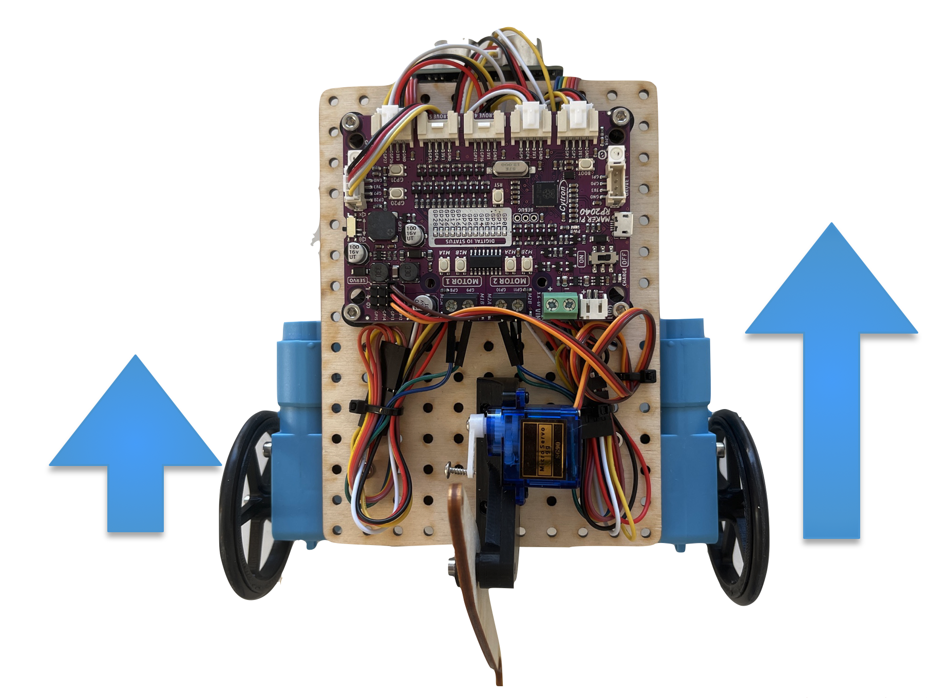
As you just saw, two unequal motor powers cause the robot to move forwards in a sweeping arc. The radius of the turn depends on the difference between the motor powers: a larger difference between the wheel speeds results in a tighter and a smaller radius turn, while a smaller difference results in a wider turn and a larger radius. Try running a couple of different combinations of motor speeds to get a feel for this relationship.
Making a swing turn
If one of the wheels is not moving while the other wheel is turning, then the robot will make a pivoting turn where the center of the robot's rotation will be on the non-moving wheel. For example, if the right wheel is turning and the right wheel is fixed, then the robot will make a turn that pivots on the left (non-moving) wheel.
The robot's path is circular, with the turning wheel (left side) forming the outside of the circle and the pivot wheel being the center. The radius of this circle will be the distance between the wheel centers.
Point turn
Another type of turn is where the left and right wheels turn in at an equal speed but in opposite directions. With this turn, the center of rotation is approximately between the left and right wheels, causing the robot to turn in place.
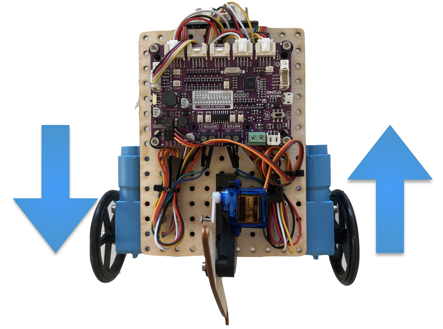
Generally, point turns are considered the most useful of the turning types, as the center of the robot remains stationary during the turn and is the fastest of the turns.
Note: The turning center of the robot is the center point between the two drive wheels. This is not necessarily the exact center of the robot, and for these robots is likely a bit farther back.
Mini-Challenge: Running in Circles
To exercise our new skills in controlling the robot's driving, let's try making a function that can drive in a circle of a specified radius.
Python Programming Note:
To make a function, you first start with the following syntax:
def func_name(parameters):
Then, all code you want to run within that function gets indented one level on the following lines. To call this code, inside the main() function where you were writing your code earlier and add the following call:
def main(): func_name()
To give your new function some context, like the radius you want the robot to drive, you include that value inside the parenthesis. Also, note that the turn_radius function comes before the main function. This is important since Python can not call a function before it is defined.
def turn_radius(radius): print(f"turning on a radius of {radius}")
def main() turn_radius(10)
We will need to use a sweeping turn, as we saw earlier. The ratio between the wheel speeds is what specifies the radius of the turning, as is specified in this formula:
MotorEffortRatio = (2⋅radius+trackWidth) / (2⋅radius−trackWidth),
where the trackWidth is the distance between the two wheels. The output of this formula is a ratio, which can be used to get the wheel speeds by setting the outside wheel to motor effort 1 and having the inner wheel be set to 1 / MotorEffortRatio
Getting Encoder Feedback
When you tested different motor efforts in the last section, did the robot ever move perfectly straight? On many robots, the robot will curve even when trying to go straight due to small differences between the left and right motors. Conveniently, the motors have sensors that allow us to measure how far they have turned, called encoders. Let's use them to try and fix this issue
What are encoders?
Encoders are sensors built into the motors that track how far they turn. You can access them using these two functions:
drivetrain.get_left_encoder_position()drivetrain.get_right_encoder_position()
These methods return how far the wheels have rotated since the start of the program in terms of the rotations since the program began. Additionally, you can also reset the encoders at any time using this method:
drivetrain.set_encoder_position(left_distance: float, right_distance: float)
Resetting the encoder values could be useful for making your logic more readable, which you will explore in the next section.
Using the Encoder Values:
Let's start by taking a look at that issue from earlier:
def main(): while True: drivetrain.set_effort(0.8,0.8) left = drivetrain.get_left_encoder_position() right = drivetrain.get_right_encoder_position() print(f"Left Encoder Position: {left}") print(f"Right Encoder Position: {right}") time.sleep(0.01)
Note: The time.sleep(0.01) function tells the program to sleep for 0.01 seconds before looping again. Sleeping is good in a loop when you are printing a lot. This allows the message to finish showing in the Mu program before sending the next one.
Run this code, and see how far off the left motor position is from the right!
Take a moment to consider how we might try to fix this.
A related problem: Mini-Challenge
Try to write a program where the robot sits still while checking to see if there is a difference in the encoders. When there is a difference, try and correct for that difference.
HINT: You will need to use a while loop. Test it by trying to turn the robot by hand (don't pick it up; try to spin the wheels) and see that it corrects itself.
If the robot does not fully correct, that is likely because the wheels slid a bit along the ground as you were turning the wheels, and is not something that needs to be fixed in code.
Putting it together
What if we used the corrective code you just wrote to try and fix this problem?
In our first example, the effort values were just constants. In the second, the effort values were dependent on the encoder positions, or perhaps more accurately, the differences between them. What if we were to add these two terms together?
Give that a try. Did that solve the arcing problem? If not, try scaling the difference between the encoder values (called the error) by some constant to see if a stronger correction is the solution.
The Last Step
The last part that we can add to this loop would be an exit condition. Currently, our code will try to drive straight forever, which is not very practical. By either saving the initial encoder positions or resetting them, we can find the distance traveled since the start of the drive loop and use that to figure out when we've reached our target.
An example of this, excluding the drift corrections you just added:
def go_distance(distance: float, speed: float): # Save the initial conditions starting_left = drivetrain.get_left_encoder_position() starting_right = drivetrain.get_right_encoder_position()
# Calculate needed wheel revolutions rotations_to_do = distance / (drivetrain.wheelDiameter * math.pi)
# Initialize variables to be used inside of the loop left_change = 0 right_change = 0 # Loop while your forward distance traveled (avg between left and right) # is not yet greater than the specified distance while (left_change + right_change)/2 < rotations_to_do: left_position = drivetrain.get_right_encoder_position() right_position = drivetrain.get_right_encoder_position() left_change = left_position - starting_left right_change = right_position - starting_right drivetrain.set_effort(speed, speed) # Delay a little so we aren't polling data from the encoders constantly time.sleep(0.01) drivetrain.stop()
Add this style of breakout condition to your code and test it by trying to go various distances.
Mini-Challenge: Mixing it Up
You may have noticed that your drive function occasionally will overshoot the target by a tiny amount. Try making another addition to your drive code from before to get the robot to slow down as it approaches the target distance. A simple change like this may make the movements of your robot more accurate.
Calling Drive Functions
In the last section, you wrote your own drive functions for going straight and turning. However, we have some written for you that you can use if you would rather not use your implementation:
drivetrain.go_straight(distance: float, speed: float = 0.5, timeout: float = None) -> booldrivetrain.go_turn(turn_degrees: float, speed: float = 0.5, timeout: float = None) -> bool
These versions of the drive functions have a few extra features we didn't cover in the last section, such as an optional timeout if you anticipate the robot being unable to reach its target position for any reason.
Calling the Drive Functions:
Similar to most of the code you've written so far in this section, we call these methods from inside of def main():, located within code.py:
def main(): # Drive forwards 20 cm and then turn 90 degrees clockwise drivetrain.go_straight(20, 1) drivetrain.go_turn(90, 0.8)
So now that we have the fundamentals of driving down, what else can we do?
Mini-Challenge: An A-Maze-ing Path
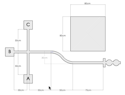
[Picture of 1001 maze (with dimensions)]
If we wanted our robot to navigate this maze, what would we do? Try breaking down the path into simple "drive straight __ cm" and "turn __ degrees" segments. This will allow us to easily convert real-world instructions into code for the robot.
Once you have your path written out informally, try converting that into instructions for the robot using the go_straight and go_turn functions. Place your robot into the maze and run your code. If your robot touches the tape at any point, try to adjust the distances and turns so that it doesn't.
A Shapely Surprise
Let's take the ideas we just exercised for the maze and do something simpler. Let's try to get the robot to drive in the shape of a square. You can choose how big you want the square to be; for this exercise, it doesn't matter. Follow the same steps as before, and write down the segments in pseudocode (words describing what the code will do informally) before translating that into actual code.
You may notice that this code is pretty repetitive, consisting of the same two instructions four times. There's got to be a cleaner way of doing that.
Python Programming Note: For Loops
Similar to the while loops we covered earlier, for loops are a special type of loop usually used to repeat some lines of code a specified number of times. The syntax for a for loop is as follows:
for counter_name in range(number_of_loops): # Loop content goes here
As a for loop cycles, "counter_name" becomes a variable equal to the loop number that is currently occurring, starting at zero. This means that on the third time running the loop content, counter_name = 2.
Mini-Challenge: An Application
Now that we know about for loops, we can try a new approach to driving. Take your square driving code and adapt it to have the robot outline a triangle instead of a square. Then, rewrite it using a for loop.
Waiting for Button Input
You may have noticed that your code runs immediately after uploading it. This is nice sometimes, but sometimes you aren't coding in the same place you will be running your code, and the robot suddenly driving itself off the table isn't an ideal result. To run the code on command, we can use the onboard buttons to tell the code when to run.
Using Button Inputs
There are two buttons on the board from which we can get input, labeled as GP20 and GP21, respectively. As such, there are two functions we use to check if either one is being pressed:
buttons.is_GP20_pressed()buttons.is_GP21_pressed()
These methods both return a boolean value (a True or False), which means they can both be used directly as a condition for a while loop.
Waiting for a button input
Since these functions return True if they are being pressed and False if they aren't, waiting for a button press is as simple as:
while not buttons.is_GP20_pressed(): time.sleep(0.01)
The time.sleep() statement is necessary to avoid overloading the button pin. Checking the button 100 times a second is still more than enough precision for almost any application.
Waiting for a button input allows us to start our program on command, which is a very convenient feature.
Try putting this code at the start of any programs you have written so far. Take note of how the program begins as soon as you press the button.
Mini-Challenge: Multiple Button Presses
But what if we instead wanted to check for multiple consecutive button presses? If you place the previous code segment a few times, you may see that pressing the button once may allow for all or most of the checks to pass, as you aren't telling the code to wait for you to release the button before registering the next check.
Try writing your own implementation where you have to press either button three distinct times before your program begins.
Using the Sample Code's Implementation
We have provided some sample code to handle the waiting for a button press. But first, you have to tell Python to import that code into your program. Use the following line at the top of your program to import that code.
from SampleCode.sample_miscellaneous import *
This line gives everything in code.py access to all the functions in sample_miscellaneous.py, including wait_for_button().
It can be used very simply by placing the call at the beginning of your def main():
def main(): wait_for_button() # Your Code Here!
Robot Performance Challenge: Driving
The objective of this challenge is to test the skills you've developed in this section.
Part 1: Function Creation - Polygon
The first part of this challenge is to create a function that takes in two parameters, a side_length and a number_of_sides, and then has the robot trace the outline of a polygon that has that number of sides of that side length.
Part 2: Understanding the Code - Circle
The second part of this challenge is much harder. Create a function that takes in just one parameter, a radius, and has the robot trace the outline of a circle of that radius, starting at any point on its perimeter and ending on that same point.
Distance measuring overview
Topic Description
In this module, students will:
- Understand the basics of measuring distance and its application
- Learn to use distance sensors to determine the robot's location with respect to the target.
- Use reading from the sensor to avoid obstacles or stop before the object
- Learn the concept and basic application of On/Off control and Proportional Control
- Write a quick program for Robot Wall Follow
At the end of this module, students will be able to:
- Determine the robot's current position relative to the target
- Get their robot to stop before the mark or avoid obstacles using sensors
- Use Proportional Feedback Control to control the robot's speed and achieve more accurate results.
- Develop an autonomous wall-following program
To complete this module, review and do the tasks outlined in each section and successfully pass the module quiz at the end.
Measuring Distances
Real-world examples of distance sensing in robot systems
In the programs you have written so far, the robot has been able to drive measured distances based on the circumference of the wheels and the number of rotations. This works as long as the objects the robot drives toward are always precisely the same distance away. But what happens if the robot tries to manipulate an object that might be different distances from run to run? If the robot could see the object, then it would always be able to drive to the object and stop and a repeatable distance from it. For example, if the robot's task is to pick up a box with its arm that extends.
Welcome to the distance measuring module! The ability to measure the distance between a robot and the objects in its surrounding environment is crucial. This information allows the robot to avoid collisions and determine its current location with respect to the target.
Applications
Autonomous Vehicles
Distance measuring is a fundamental feature of Tesla's Autopilot software for self-driving cars. Autonomous driving is a complex task and requires an incredible amount of information on its surrounding obstacles to avoid a collision. Measuring the forward distance to an obstacle allows the vehicle to maintain a healthy distance. Measuring sideway distance determines whether it is safe to merge highway lanes. While parking, measuring backward distance informs whether it is safe to continue backing up.
Tesla uses radar, a system using radio waves, for long-range sensing. A device known as a transmitter produces electromagnetic radio waves, which reflect back after hitting an object. Another device, a receiver, captures this reflected wave to calculate the object's distance based on the wave's travel time and speed.

Marine Echolocation
Measuring distances isn't only important on land; it is also important underwater as well! Submarines use sonar, a system using sound, to navigate in the murky waters, measure distances from nearby objects, and detect notable presences in their surrounding environment, such as sunken ships.
Like radars, sonar detects objects by transmitting ultrasonic waves and captures the reflected echoes. Based on the travel speed and time of the wave, the distance to the object can be calculated.

Animal Echolocation
While integrating these distance-measuring sensors into a robot is impressive, animals do it better!
Bats navigate through dark caves and find food through echolocation by emitting high-frequency sound waves using their mouths. They listen to the echo of the sound waves bouncing back from the environment with their highly sensitive ears, allowing them to determine the size, shape, and texture of objects.
Similar to bats, whales also use echolocation to navigate underwater and locate food. They emit high-frequency clicking sounds using their nasal passages.
Distance Sensors
Distance Measuring Sensors
So, what are some sensors that allow you to measure distances?
Mechanical Sensors
If you touch it, then you know it's there. Mechanical sensors detect some form of mechanical deformation (bend, press, etc.) and translate that into an electrical signal. This is a very naive but still valid way to approach distance measurement. The obstructing object could activate a mechanical switch upon contact, signaling its presence.
An example of a mechanical sensor is a Whisker Sensor. The whisker itself is a long flexible piece of metal that can bend and trigger a mechanical witch to notify the obstacle ahead. Whisker sensors can consist of multiple whiskers to sense obstacles from multiple directions.
Reflective sensors
Lidar (Light Detection and Ranging), Sonar (Sound navigation and ranging), and Radar (Radio Detection and Ranging) all follow the same principle. A transmitter emits light, sound, or radio waves, which bounce back from an obstructing object, resulting in echoes. A receiver captures these echoes, allowing for the calculation of distance based on the travel time of the wave.
Using the Ultrasonic Sensor
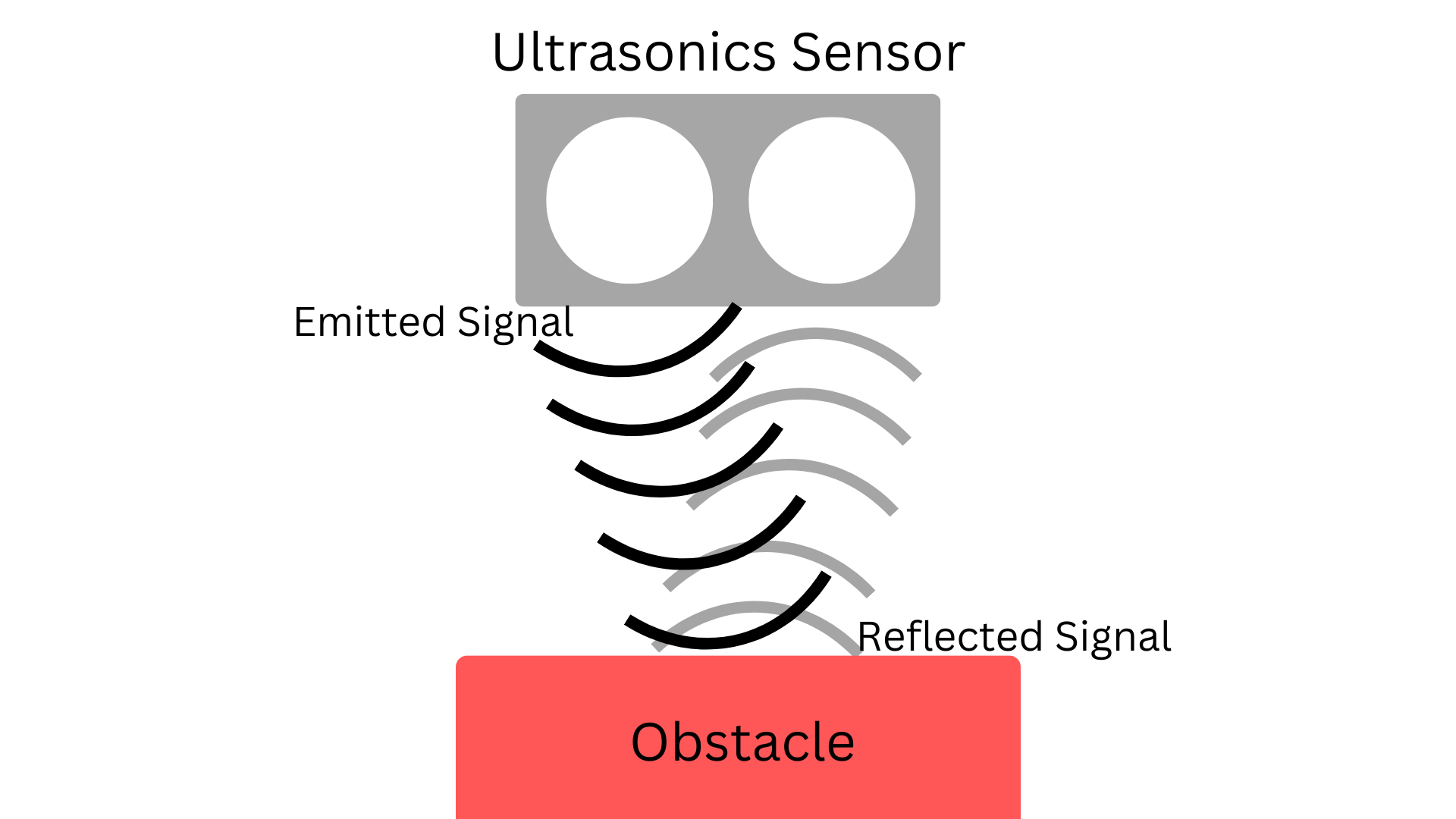
We will be using an Ultrasonic Sensor which is one type of Reflective Sensor that uses Sonar to measure and calculate the distance. We have just one function for getting input from the ultrasonic sensor.
sonar.get_distance()
This function returns the distance, in cm, from the sensor to the nearest object.
Mini Challenge: Show the distance
Try writing code that checks the distance every 50 ms (0.05 seconds) and prints the distance to the nearest object in front of the robot.
Controlling Behavior: On/Off Control
The main purpose of sensors is to introduce feedback into the system. During actuation, the state of the robot and its environment continuously changes. Feedback informs the system how much the state has changed and how much more the state should change. Feedback introduces more control over autonomous behavior - a fundamental characteristic of all intelligent robots!
Python Programming Note: If Statement
An if statement will execute its inner code block if its specified condition is met. For example:
if True: print("Hello World!")
The if statement above will print "Hello World!" because its condition is true.
if False: print("Hello World!")
The if statement above will not print "Hello World!" because its condition is always false.
int i = 3if i < 5: print("Hello World!")
The if statement above will print "Hello World!" because the variable "i" is less than 5, satisfying the condition.
On/Off Control
The most basic form of control is called On/Off control. In this control scheme, an actuator is turned on until a certain condition is met. When the condition is reached, the actuator is turned off.
In our distance measuring example, we are tasked to drive the robot forward until it is 10cm away from an object. Here is the procedure for On/Off control:
1. Drive the robot forward until the sensor measures a distance under 10cm.
2. Command the robot to stop driving.
3. If the measured distance is larger than 10cm, repeat these steps.
def on_off_control(target_distance: float, on_effort: float): while True: distance = sonar.get_distance() if distance < target_distance: drivetrain.set_effort(on_effort, on_effort) else: drivetrain.set_effort(0,0)
Mini-challenge: Obstacle Avoidance
See if you can write code to help the robot avoid bumping into obstacles:
- The robot drives forward while continuously measuring the distance between itself and incoming obstacles.
- When the distance decreases to a certain threshold, tell the robot to turn to a certain angle and resume driving in the new direction.
- Experiment with different distance thresholds and turning angles!
Controlling Behavior: Proportional Control
Proportional Control
There are several inherent problems with the on/off approach.
- inertia exists, and the robot might drift forward a few centimeters, overshooting the 10cm target.
- there are only two speeds for driving: a forward speed or none at all.
We introduce proportional control to address the concerns from On/Off control.
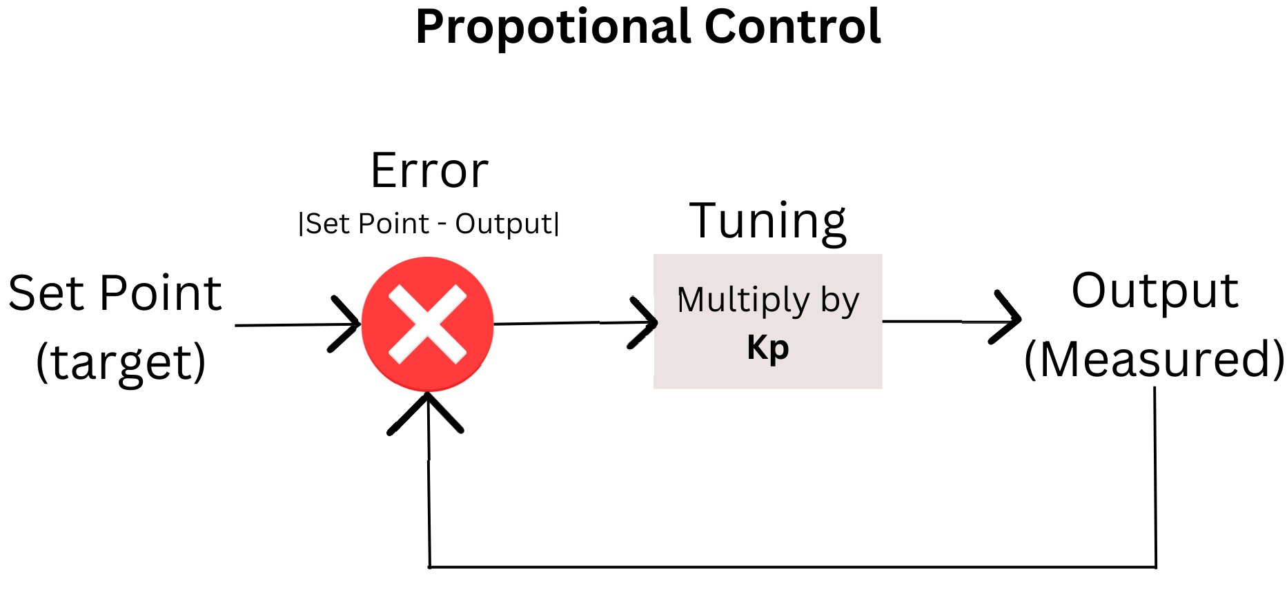
What is proportional Control?
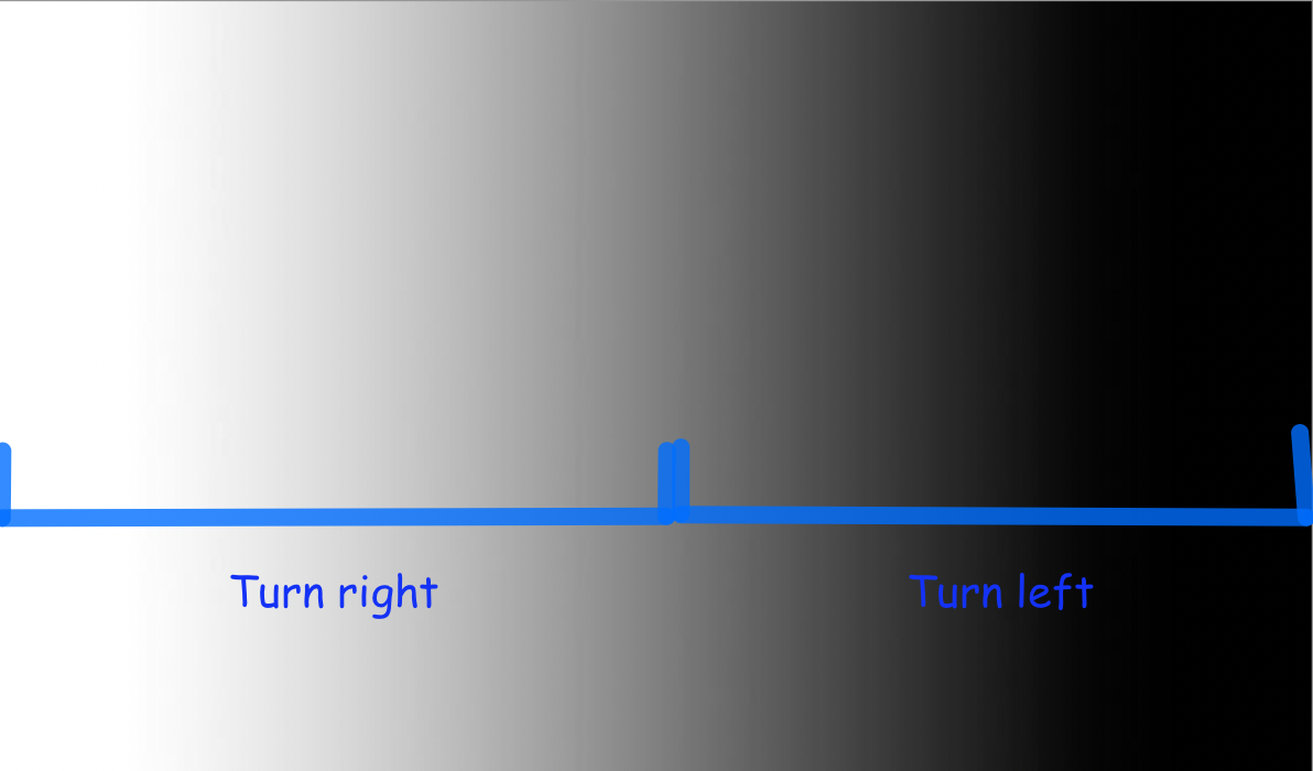
Proportional control is a linear feedback control system. It uses response in proportion to the difference between what is set as the desired target, a set point value, and the current measured value from the output to achieve better and more accurate output from the next cycle. We will call this difference error or offset.
In other words, the effort will be adjusted accordingly to the error value to achieve the target point. For example, in the below example, more error means higher speed and vice versa.
Error is not the only thing being used in Proportional Control. A Controller Proportional Gain (Kp) is a value that can help tune the finest of the robot's behavior. Kp determines the ratio output response to the error signal. Finding a good Kp value is commonly vis trial and error to observe how the robot will react to a different value.
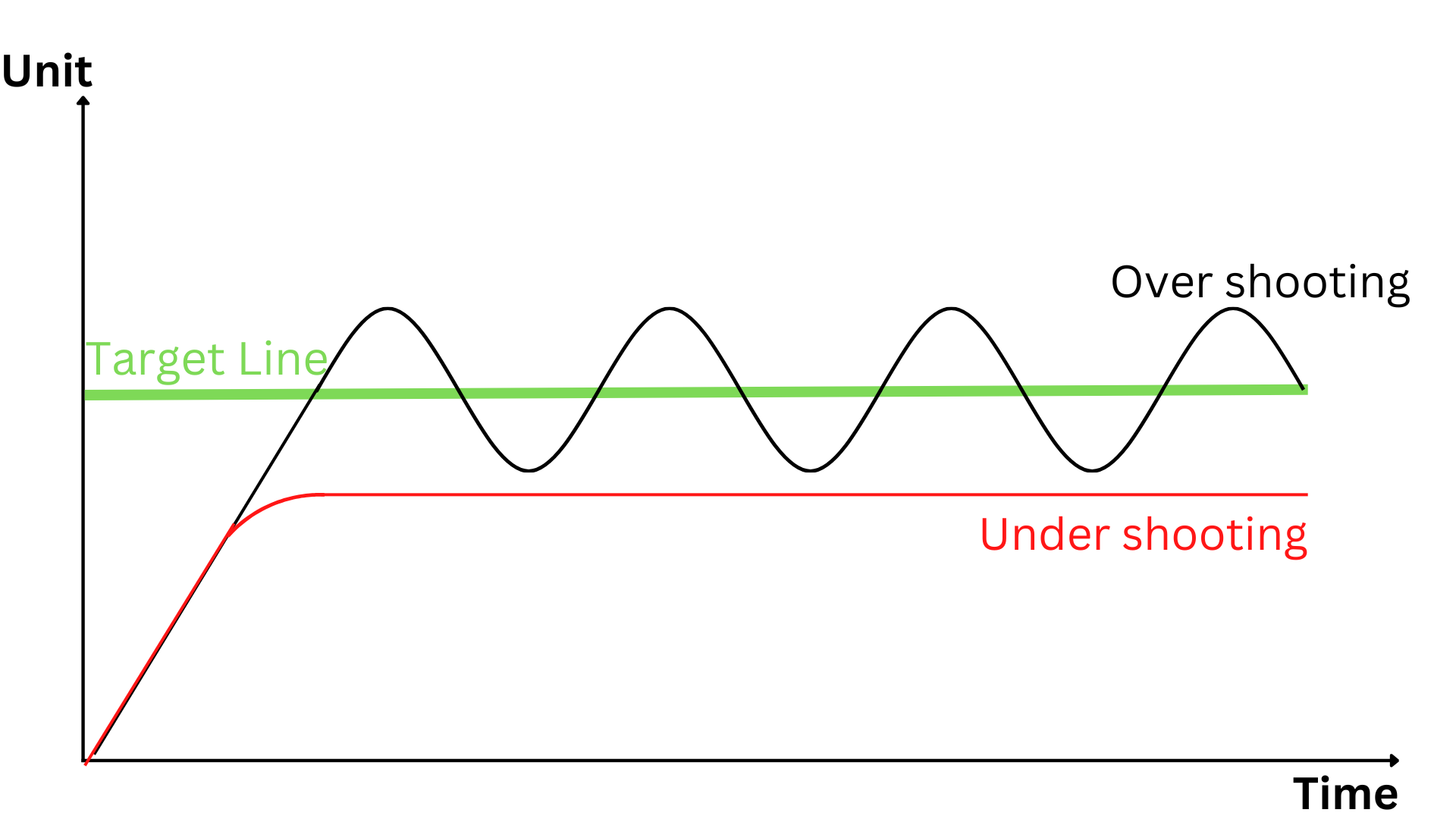
Tuning Kp
One thing you will notice when first using Proportional Control and tuning Kp is the overshooting or undershooting of the target. Undershooting target, you might observe that your robot never quite gets where you want, either in terms of distance, speed, or more. With overshooting the target, you might potentially see your robot dancing in oscillation back and forth. This behavior happens when your robot overshoots the target, tries to adjust by going in a different direction, overshoots again, and the process repeats. Knowing this behavior can better help you tune and change your Kp value; you can minimize the overshoot and undershoot behavior and get as close to the target as possible.
Other Controllers
Besides Proportional Control, there are also Integral Control and Derivative Control.
- Proportional Control: Control the error of the target and output to help reach the target.
- Integral Control: Control the sum error over time to help archive the target stably over time. Integral Control can eliminate the steady-state error or the oscillation from proportional control.
- Derivative Control: Control and detect the change in error over time to help achieve the target quickly.
Together, these three controllers are known as PID Controller (Proportional, Integral, and Derivative Controller). Each controller requires its own value, Kp, Ki, and Kd, accordingly, which increases the difficulty in tuning. Depending on applications and usages, you can find different combinations between this controller or by themselves, such as PI Control (Proportional and Integral Control), PD Control (Proportional-Derivative Control), and many more.
In this session, we will only focus on Proportional Control. You are free to explore the use of the other control algorithms, integral and differential.
Apply Proportional Control to Measuring Distance
In proportional control, we specify the effort of an actuator based on the error between the current state and the target. In this example, the error will be the error between the currently measured distance from the sensor and the target of 10 cm.
In our distance measuring example, we are still tasked to drive the robot forward until it is 10cm away from an object. Here is the procedure for Proportional control:
1. Measure the distance between the robot and the wall.
2. Calculate the error between the current and desired distance.
3. Multiply the error by a constant to calculate the effort.
4. Clamp the effort such that it is within the defined effort range. (Done automatically by set_effort)
5. Set the effort to the motors.
6. Repeat these steps.
In Proportional control, the robot's speed is directly correlated with the error between its current location and the desired distance from the wall. The speed is high when the robot is far away from the wall. When the robot is right on the target, there is no speed because there is no error. This addresses external disturbances in the system. If the robot is pushed away or towards the wall, the calculated error will increase, increasing the robot's speed to correct its position.
The value of the constant KP needs to be tuned based on the sensor and motor effort range. Therefore, it is often determined by experimentation. If the constant is too small, the effort of the actuators will not be able to induce motion. If the constant is too large, the compensation would be too large. This would cause the system to repeatedly overshoot its target, causing oscillation. Try the code below and try changing the value KP to get it tuned so your robot operates.
def proportional_control(target_distance: float): KP = 0.2 while True: distance = sonar.get_distance() error = distance - target_distance drivetrain.set_effort(error*KP, error*KP) time.sleep(0.01)
Mini-Challenge: Following a Wall
Watch this video of the robot following a wall using a Proportional controller.
Make sure the sonar sensor is mounted sideways to measure the distance of a wall parallel to the robot's driving motion. Try to adapt the code just given to you to make a program that does the following:
- The robot steers away when the sensor detects that the robot is too close to the wall.
- When the sensor detects that the robot is too far away from the wall, the robot steers closer.
- When the error is large, the robot compensates more.
- When there is no error, the robot generally follows a straight line.
Navigation and line following overview Overview
Topic Description
In this module students will:
- Acquire the basics of robot navigation
- Learn to use the reflectance sensor
- Write a quick program for Robot line following
At the end of this module, students will be able to...
- Discuss the robot navigation concept
- Get their robot to follow a line
- Develop simple sensor logic control for robot decision making
To complete this module, review and do the tasks outlined in each section.
Using the Reflectance Sensor
Detecting the line
The XRP robot is not only able to measure distances with its rangefinder but also can use its two analog reflectance sensors on the front underside of the robot to measure how reflective the ground surface is. This is particularly useful for a specific use case - detecting and following lines!
Navigation
The goal of navigation is to find the best route from the starting point to the destination within an environment. Navigation is especially helpful for avoiding obstacles and staying on the path.
The reflectance sensor
This sensor consists of an infrared transmitter and a receiver. The transmitter emits infrared light, which gets reflected from colored obstacles (for our curriculum, the colored obstacle is the black line that the robot would follow). The receiver absorbs and senses how much infrared light is reflected from the nearby obstacles. Based on the intensity of the absorbed light, logical decisions could be made by the robot to complete certain tasks, for example, following a line.
The API provides two library functions to read information from the reflectance sensors:
left = reflectance.get_left_reflectance()right = reflectance.get_right_reflectance()
Both of these functions return a value that ranges from 0 (white) to 1 (black). However, these sensors are separated only by around a centimeter - why do we need two sensors instead of one? Later in this module, we will discuss how integrating the data from both sensors onto our code can yield more accurate results.
Let's consider a previous exercise - using the rangefinder to drive until some distance from the wall. The code looks something like this:
drivetrain.set_effort(1,1)while sonar.get_distance() > 10: time.sleep(0.1)drivetrain.stop()
Here, we command the robot to start going forwards, keep polling our rangefinder at regular intervals, and when we dip under the 10 cm distance, we break out the robot and stop the drive motors.
Consider a similar use case for the reflectance sensor: driving forward until a dark line is detected.
How could we go about programming this? Well, let's consider what values the reflectance sensor would read throughout this program.
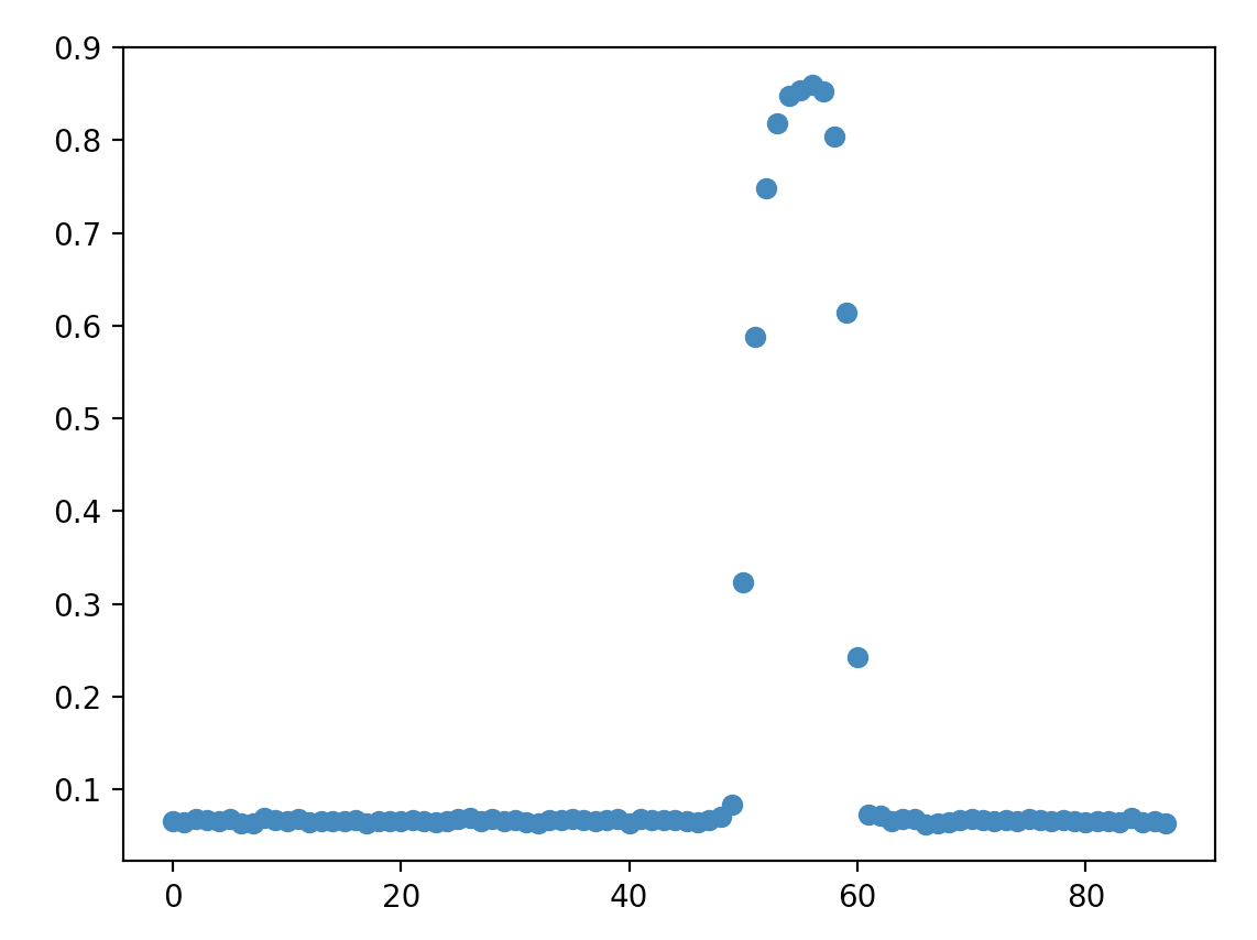
This plots the readings of the left reflectance sensor on the y-axis over time on the x-axis, where the robot starts on a white surface and then crosses over a black line.
As shown in the plot, our reflectance sensor gives readings close to 0 while on the whiteboard but then jumps close to 1 when it sees the dark line before going back down. Could we adopt a similar code structure with a while loop as above to achieve this?
The key lies in the condition of the while loop - what causes the while loop to terminate. In this case, we want to check whether the sensor's reading has dipped below a certain value, which would indicate the detection of the dark line. Note that we don't get values that are exactly 0 or 1 - surfaces never fully reflect or absorb heat - so we can't have a while loop condition like:
while reflectance.get_left_reflectance() != 1:
A condition like this means that the robot would continue going forward until it detected a black surface, which is quite unlikely to happen. Instead, by considering any value over 0.7, for example, as "black," gives us a considerable margin of error for different variations of dark surfaces. So, the code should consist of starting the motors, waiting until the reflectance sensor's value jumps above a value (i.e., 0.7), and then stopping the motors.
Mini Challenge: Line Detection
- Write a program to go forward until a black line is detected. It should look like the video above.
Following the line: On/Off control
Now, let's turn our attention toward one of the core challenges in the final project - following a line. In the project, the robot will need to drive to multiple locations - but doing this blindly can result in the robot drifting in an unexpected direction - the drive motors may not be rotating at the exact same speed resulting in the robot moving in a small arc. The robot might not even be aimed in the right direction when going forwards.
By following a line, we can ensure that the robot stays in the exact path it should, eliminating drift over time. But how?
Consider using one of the reflectance sensors. As a refresher, gives a reading from 0 (black) to 1 (white). Assuming that the reflectance sensor is approximately at the center of the robot, it will at least partially read the black line when the robot is centered on the line. What logic would we need if we wanted to follow the center of the line?
If the reflectance sensor reads black, it means the robot is perfectly on the line, and we'd want to go straight, setting the motors at the same speed. But if the reflectance sensor reads grey or white, it would mean that the robot is partially or completely off the line. We'd want to correct this by steering it back to the center, but does it turn left or right?
Unfortunately, there's no way to tell. The robot has no way of knowing in which direction it is drifting off the line. Instead, try following the edge of the line. If we try to follow the left edge, there are two possible states in which the robot reacts.
- If the sensor reads closer to white, we're too far to the left, so we need to turn slightly to the right.
- If the sensor reads closer to black, we're too far to the right, so we need to turn slightly to the left.
And that's it! We want to keep polling (getting the value of) the reflectance sensor quickly and, at each time, determine whether it's closer to white (with a value less than 0.5) or closer to black (with a value greater than 0.5), and depending on the result, either set the motor to turn right (set left motor speed to be faster than right) or turn left (set right motor speed to be faster than left).
This seems like a solution involving an if-else statement. Our condition would be related to whether the value is greater or less than 0.5.
Python Programming Note:example of an if-else statement.i = 21if i > 20: print("greater than 20")else: print("less than 20")
Mini Challenge: Line Following
Follow the left edge of a black line by turning right when the sensor reads closer to white and turning left when the sensor reads closer to black.
Following the Line: Proportional Control with 1 Sensor
The perks of proportional control
Let's circle back to the previous exercise - following the line by either turning left or right depending on whether the robot is situated to the left or the right of the line. The following video shows how it behaves.
What is immediately striking about following the line in this way? Well, the robot must constantly oscillate in order to stay on the edge of the line, because even the smallest deviation from the edge of the line results in the robot wildly turning to compensate. In addition, it does not react any more forcefully to bigger deviations like when the line starts curving, and as soon as it loses sight of the line, it has no way of recovering.
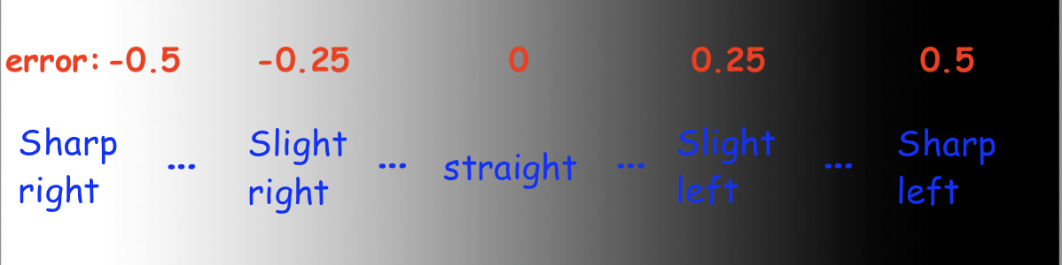
Instead of only having two cases, it seems like we'd want a whole bunch of cases, for anywhere from a sharp left turn to going perfectly straight to a sharp right turn and everything in between, based on whether the reflectance sensor is completely on white, grey, black, or somewhere in between.
Having a long chain of if-else statements doesn't sound fun. Perhaps we can look at this with a completely fresh approach?
From the previous module, we looked at proportional control to smoothly control the robot's distance to the wall using the distance sensor. Can we use the same concept here?
Calculating error
With proportional control, we have an error value we desire for it to tend to zero, and some motor output is controlled proportional to the error to minimize that error - in the case of maintaining a certain distance to the wall, the error was the difference between the target and actual distance, and the output was the speed of both drive motors. In the case of line following, the error is the difference from 0.5 - since ideally, the robot follows the grey edge of the line and goes straight - and the motor output is how the robot should turn.
So, we can obtain error value with the following code:
error = reflectance.get_left_reflectance() - 0.5
Above, we subtract 0.5 to normalize the reflectance value: the error is negative when the robot is too far left and needs to turn right, and positive when the robot is too far right and needs to turn left. Let's put that code into the test. We can put it in the loop, print out the error at each iteration, and move the robot around the line to see how the error changes. The code is as follows:
while True: error = reflectance.get_left_reflectance() - 0.5 print("Error:", error) time.sleep(0.01)
Implementing proportional control
Based on the computed error, we want that to determine how much the robot turns.
Remember: making the robot turn is simply setting the left and right motors to different speeds. So, the solution is to set a base speed - say, 0.5 - that both motors move at when the error is at 0. Then, have the calculated error influence the difference in speeds between the two motors. As explained through code:
drivetrain.set_effort(base_speed - KP*error, base_speed + KP*error)
This would be run inside the loop. The base_speed represents the average speed of the motors, no matter how much the robot turns. KP scales how much the robot should turn based on the error - a higher KP means the robot will react more violently to small deviations in error.
Let's do a sanity check to make sure the code makes sense. We assume base_speed = 0.5 and KP = 1. If the reflectance reads whitish-grey and yields a value of around 0.25, the error would be -0.25, meaning that the left motor's speed is 0.5 - 1*(-0.25) = 0.75, and the right motor's speed is 0.5 + 1*(-0.25) = 0.25. Motor speeds of 0.75 and 0.25 would indicate a turn to the right, and the code does as desired.
This is a video illustrating line following with one-sensor control. Notice the smoother tracking compared to on/off control, yet the robot is still unable to recover from the last bend because even a small amount of strafing from the line results in the robot completely losing where it is. Also, the KP value was not equal to 1 here; it's up to you to figure out the best KP value for your bot.
Mini Challenge: Proportional Line Follow
- Write code for the robot to follow the line with proportional control, as shown in the video above. Note: this isn't much more than calculating the error as shown in the previous section than integrating the above line of code in a loop.
- Play around with the value of KP. How does a higher or lower KP affect the amount of oscillation when following the line, and how responsive is the robot to curved lines? What is the optimal value of KP?
Following the Line: Proportional Control with 2 Sensors
Motivation
Line following with proportional control using one sensor is quite an improvement to on/off control. Yet, it's not perfect - if the reflectance sensor crosses over the center of the line, the robot can't recover.
The issue is - the robot has no way of knowing which side of the line it is following at all! If it sees the right edge of the line, it will assume it still is detecting the left edge, and thus keep turning right past the point of no return!
It would be neat if we could actually follow the center of the line and can recognize both cases in which the robot drifts to the left or the right of the center of the line, and makes a correction. This would largely increase the "controllable" range of what the reflectance sensor sees and can correctly react to. Conveniently, it seems like we haven't yet made use of the second reflectance sensor on the right...
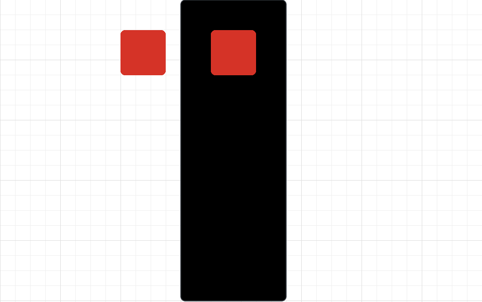
If we recorded the reflectance of both sensors as we moved the robot around the line, there are a few major "categories" of behaviors the robot would perform. For a minute, assume the rectangle is a black line, and the two red squares are the location of the reflectance sensors.
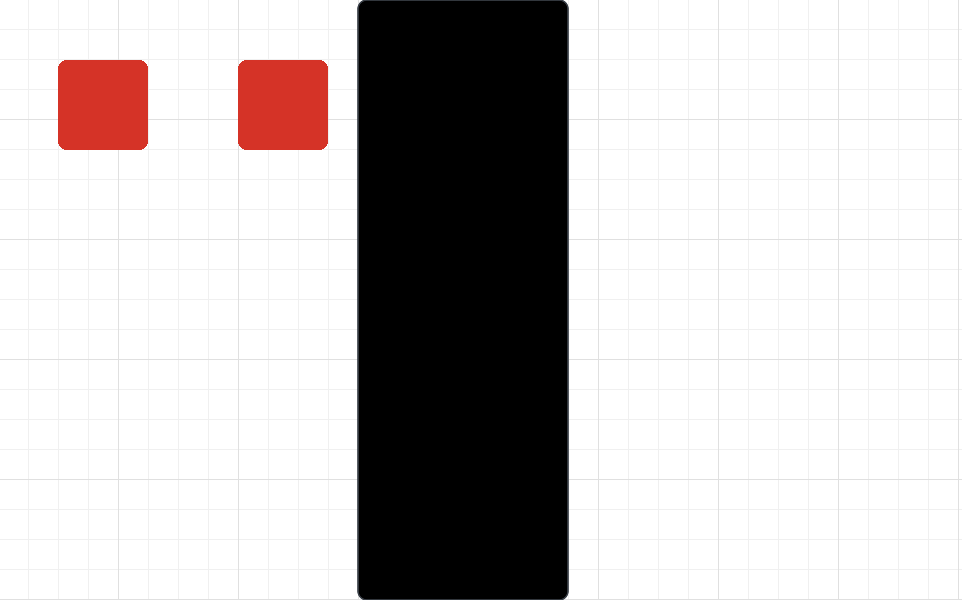
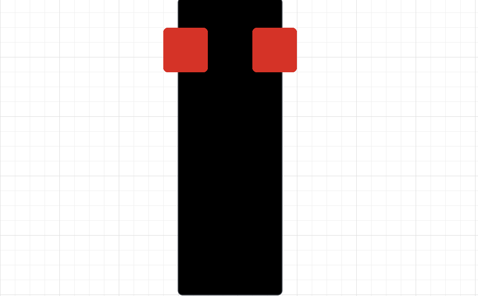
So, how can we effectively combine the readings of the left and right reflectance sensors using proportional control to have the robot follow the line? There's quite an elegant solution that I encourage for you to try to figure out yourselves before the answer is revealed.
Implementation
The big reveal:
error = reflectance.get_left_reflectance() - reflectance.get_right_reflectance()
At the beginning, this line of code may not make a lot of sense - but let's dissect it. Remember our previous convention of positive error, meaning the robot is too far left and needs to turn right, and vice versa.
In this case, if the robot is following the left edge of the line, then the left sensor detects close to white while the right sensor detects close to black, and so error = (0) - (1) = -1, and the robot turns right. On the other hand, if the robot is following the right edge of the line, error = (1) - (0) = 1, and the robot turns left. When the robot is right at the center, both sensor values are the same, so the error is 0, and as the robot starts drifting towards either direction, the magnitude of the error increases, and thus the robot compensates accordingly.
The most interesting case is when the robot is completely off the line - in this case, both sensors read white, leaving an error of (0) - (0) = 0, so the robot goes straight. Given that the robot wouldn't know which direction to compensate if it was completely off the line, this seems like a reasonable result.
And so, our final code is as follows:
KP = 1 # experiment with different values of KP to find what works best while True: error =reflectance.get_left_reflectance()-reflectance.get_right_reflectance() drivetrain.set_effort(base_speed - KP*error, base_speed + KP*error)
Here's what that looks like. Note that KP used in this video was not equal to 1.
Mini Challenge: Proportional Control with Two Sensors
- Combine what you've learned with encoders to create a function that follows the line using two sensors for some given distance and then stops the motors.
- What KP value is best?
- Compare one sensor to two sensor line following. What bends in the black line is two sensor line following able to handle that one sensor line following cannot?
Challenge: Sumo-Bots!
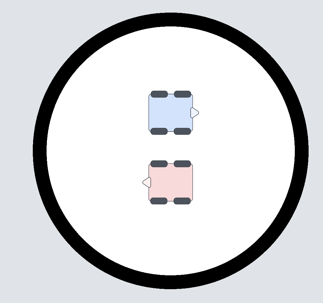
It's time for SUMO bots! Two XRP bots battle it out in the ring in a completely autonomous match to push the other robot outside of the ring.
Robots start facing away from each other in the orientation above and have one minute to knock the other robot outside. They may utilize distance sensors to detect the presence and location of the other robot and use the reflectance sensors to keep themselves inside the ring.
Hint: A basic SUMO-bots program may consist of a robot continuously point-turning until an enemy robot is found with the distance sensor and then charging at the robot until the black line is detected so that the robot stays inside the ring. However, worthy extensions include: aligning the robot to be perpendicular to the black line so that the robot is not misaligned and devising an algorithm to attack the opponent robot from the side to avoid a head-on collision and gain more leverage.
Manipulation overview
TBD
Using the servo
Controlling the servo is pretty simple, consisting of just one function to control it:
servo.set_degrees(degrees: int)
This function tells the servo to move to a position bound within [0,135], in degrees. A value above 135 will go to an angle of 135, and a value below 0 will go to an angle of 0.
Calibrating the Arm
Before we can go ahead and use the arm, we need to calibrate it to know where the maximum or minimum positions are. To calibrate the arm, complete the following steps:
- Remove the arm from the servo.
- Run servo.set_degrees(135) to set the servo to its lowest position. servo.set_degrees doesn't wait until the servo is done moving before going to the next instruction, so include a time.sleep statement afterward.
- Attach the arm so it is horizontal out the back of the robot.
To verify that it is correct, run servo.set_degrees(0) and confirm that the arm rose.
Mini-Challenge: Picking Up The Box
After calibrating, write code to back into the box, pick it up by raising the arm, and then drive forwards while carrying the box.
Integrating Servo Usage
Now that you know how to use the servo let's start integrating multiple parts of what you've learned!
Mini-Challenge: Approach and Collect
First, let's make the foundation of what you will use to pick up the box. Make a method def pick_up_box() that picks up a box directly in front of the robot. Once you have this working, we can move on to the next step.
Mini-Challenge: Line Following Approach
Now, let's expand upon that. Write a program that will follow a line until it sees an intersection, then picks up a box that was waiting at that intersection. Then, once the robot has picked up the box, have it follow the line back until the end of the line and then drop off the box at the end of the line.
If you need a refresher on Line Following and how to sense an intersection/being off the line, please refer back to Module 5.
Mini-Challenge: Locate and Secure Cargo
With the robot starting on a line, write a program that uses the ultrasonic sensor to detect cargo from anywhere on the field, then picks it up. You can assume that the cargo is turned to the correct angle for the arm to lift it. Once you have secured the cargo, return to your original position.
If you need a refresher on using the Distance Sensor to find obstacles, please refer to Module 4.
Example videos for each of these mini-challenges will be added to this section later. These are important sub-components to the final project, which is your last piece of the course.
Delivery Robot Challenge

Introduction
To help people in need during the current pandemic, you and your colleagues have decided to build an autonomous delivery robot.
Your robot will pick up food and other supplies and deliver them to residences with minimal contact, all to help fight the spread of the coronavirus.
Of course, a full-sized version will have to wait until you get millions of dollars in investments for your robotics company, but that doesn’t mean you can’t have fun dreaming with a scale model here.
Your robot will have an arm for lifting and carrying “bags” of goods and sensors to help it navigate a simple network of “streets.” Complicating things a little, not everything to be delivered is always put in the right spot for easy collection, and sometimes road construction might block your path. But you’ll still need to make it work!
The world is counting on you! Can you make it happen?
Objectives
The final project is a chance for you and your teammates to demonstrate that you can apply concepts and strategies from the course to a specific challenge. You will apply theoretical knowledge to the design of your system and use focused testing to improve the performance. The project will culminate in a demonstration where you will prove your robot’s performance. To help us understand more about your system and your process, you will also produce a report describing the system development and an assessment of how well it met your goals.
The successful team will design, build, and demonstrate a robot that can accomplish a prescribed set of tasks. To be successful, you will need to:
- Identify key performance criteria and develop a strategy for meeting your team’s objectives,
- Identify key factors that affect performance and use analysis and testing to specify them,
- Develop and apply a testing strategy to ensure performance,
- Evaluate the system performance, and
- Describe the system and your design process.
Challenge
Your challenge is to program your robot to pick up bags of supplies from known and unknown locations and deliver them to specified delivery points. The challenge is constructed such that the tasks have a range of difficulty. For example, located the free range bag and scoring them will earn more points, as will being able to navigate around the construction sign. Since you will have to perform multiple runs, reliability will be essential.
Course
The course will consist of a strip of tape (to simulate roads) with a designated place to pick up bags and three specified drop zones. Most bags will be placed at the end of the main road, though some will be placed in a “free range” zone. Figure 1 shows a typical arena, though we realize that there will be some variation in each course.
Bags
You will be expected to build your own delivery bags, for example from paper or card stock and paper clips. You should have at least two bags ready for the demo. You may “recycle” them as the demo progresses. [Insert approximate dimensions of bag that the XRP can pick up]
Collection
Most of the bags will be placed on the line at the end of the main road. You may place a piece of tape near the pickup zone to indicate where it starts, but the bags will be placed at different distances from the tape.
To earn points for collecting the free-range bag, you must demonstrate that its position can be arbitrary within the free-range zone (with the exception that you may face the bail in whatever position you deem most favorable).
Delivery zones
Each delivery zone or platform may be no larger than 10 cm in any horizontal dimension. The platforms for the delivery zones will be 4 cm [Make sure XRP can raise bags high enough, adjust this value later] above the ground. You can make them out of cardboard or any other material. To score points, each container must be placed in a delivery zone and left there (upright) long enough to prove that it is stable.
Operation
You will start with your robot on the main road and a bag in the pickup zone. On command (a press of either button on the robot), your robot will drive to the pickup zone, pick up a bag, and deliver it to the specified address, which will be determined by the button press (e.g., ’GP20’ indicates a delivery to address A, etc.). Your robot will then return to the starting point, stop, and wait for the next command.
After each delivery, you will place another bag in the pickup zone and repeat the process, pressing the button to indicate another delivery. You may recycle the bags as much as you wish.
At two random points in the demo, your instructor will place a road construction sign on the main road for 30 seconds, and you will not receive credit for any delivery during which your vehicle hits the sign.
The challenge will last 5 minutes. You may use any of the sensors that you’ve explored in this class to accomplish the challenge. Line following will be an important behavior, but collecting the free-range bags autonomously will require some creativity on your part.
[Video of a sample run coming soon!]
Scoring
[Tune point values over time]
In your run, your team should deliver as much weight as possible, plus and including the “free range” bags. Points will be allocated as follows:
- You will receive 5 points for every package you deliver to addresses A or C. However, you may only get 50 points max (corresponding to 10 packages) for each delivery address; i.e., you must deliver to all three addresses to receive the maximum points.
- You will receive five additional points for each free-range bag (20 points max) scored at address B.
- Your total score will be multiplied by the number of unique addresses you delivered bags to. That is to say, if you scored one bag to Address A and one bag to Address B, your final score would be 2 * (5+5) = 20 points. If you scored a free-range bag on top of that, your score would be 3 * (5+5+5) = 45 points
- No points will be received for a delivery where the robot hits the road construction sign.
- You will lose 2 points for each time you have to touch your robot (e.g., to put it back on the line), other than to specify the delivery zone at the start of each delivery.