Appendix B: Ex-Fix Guide For The Non-Orthopaedic Surgeon
The purpose of an external fixator (“ex-fix”) is to provide a temporizing measure to hold broken bones (usually the femur or tibia) in a reasonable position until further surgery can be performed. The ex-fix provides stability to bones that is particularly important in transfer situations in a combat zone, takes pressure off the surrounding soft tissue and joints, and provides pain relief to the patient.
There are two main types of external fixator constructs:
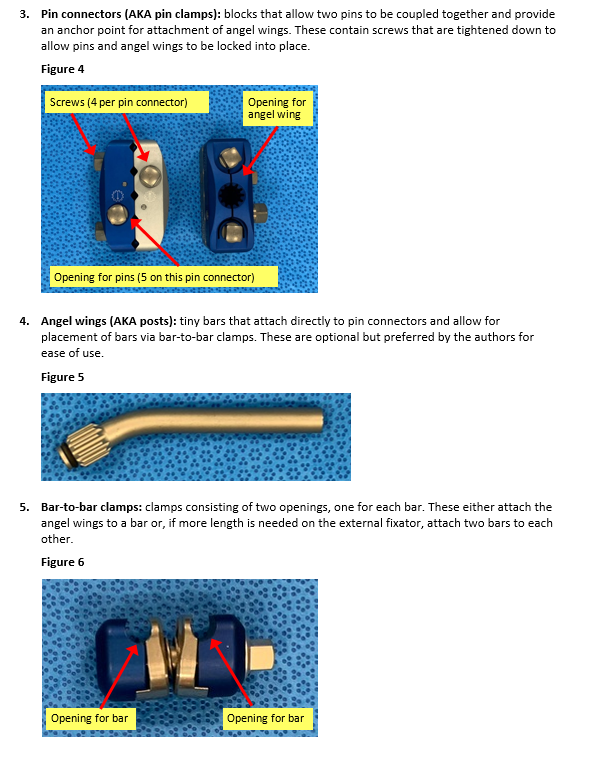
- Both sets of pins go in the same bone segment.
- Joint-spanning external fixator: one set of pins goes in one bone, and the other set goes into the adjacent bone (e.g. knee-spanning external fixator consists of pins in the femur and the tibia). These are typically performed when the fracture occurs near a joint.
The basic construct consists of the following components:
- Pins: stainless steel pins that are drilled into bone, either on power or by hand. The tips of the pins are threaded to prevent them from backing out of bone.
- 5mm pins are typically used for the femur and tibia.
- The drill tip (circled) of the pin should be advanced through the bone to allow full engagement of the threads.


Sterile Field Kit Components
Commercially available sterile field kits allow for placement of an external fixator by hand and typically consist of the following components:
- Scalpel
- Mosquito clamp
- Pins
- Bars
- Manual drill-brace: Serves dual function as hand drill as well as tightener for clamps; each end is labeled for reference (“pin end” and “clamp).
- Bar-to-bar and/or Pin-to-bar clamps
- Pin connectors: Not available in every kit. May come pre-assembled with angel wing.
Basic principles:
- Two pins (at least) are required on each end of the fractured bone.
- Pins should avoid immediate proximity to the fracture site (at least 2-3 fingerbreadths away).
- The external fixator is a tool to reduce fractured bone. Try to restore length and gross alignment.
Minimum Supplies: 4 threaded pins, 2 pin connectors, 2 bars, 2 angel wings (4 suggested), 4 bar-to-bar clamps. Note: Fluoroscopy is beneficial but not essential.
Step-By-Step Instructions (Associated photos for a knee spanning external fixator)
Pin Placement
- Identify external fixator pin sites as described above, taking care to remain in safe zones.
- Femur: Anterior or anterolateral
- Tibia: Just medial to anterior tibial crest (ridge)
- Calcaneus (heel): 1-2 fingerbreadths in front of (anterior) and above (proximal) to the posterior corner of the heel. Drill centrally-threaded pin from medial to lateral to avoid posterior tibial artery.
- Start either proximal or distal to fracture.
- Identify 1st pin site, use scalpel to make stab incision (7-10mm).
- Use a blunt hemostat to dissect down to bone (keep tips of hemostat closed).
- Insert pin perpendicular to bone (Figure 1).
- **Pearl: To drill the tibial pins, it can be helpful to start drilling perpendicular to the bone and create a divot without going all the way through the cortex, then redirect your hand so it is pointing toward the floor. This may help avoid slippage of the drill.
- Place pin bicortically—when using a power drill to insert pins be wary of excessive depth of the pin that can damage deep structures. If inserting by hand and/or without power, once the far cortex is engaged (when increased resistance is felt as the pin is turned), advance the pin an additional 6-8 full turns to reach a safe depth. When fluoroscopic imaging is available, placing pins with power is safe and effective. Hand-inserted pins can be adjusted at follow on facilities when needed.
- If the pin clamps are going to be used, slide pin connector over 1st pin to template location of 2nd pin and mark skin with pin or knife (Figure 2). If clamps are not available or desired, placing the pins in any safe location is possible followed by connection to bars with pin-bar or combination clamps.
- Repeat steps 3-6 for 2nd pin. Placing the pin parallel to the first can reduce the complexity of the fixator, but off-plane pins can increase stability. Pin placement should be decided based on the associated anatomy, fracture and soft tissue injury patterns and fixator stability (Figure 3).
- Move to proximal (or distal) pin site and repeat steps 1-8 (Figure 4).
- Tighten down the screws securing the pins of the proximal and distal pin connectors, ensuring there are 2-3 finger-breaths between the pin connectors and the skin. This is important because swelling will often occur and may lead to skin compromise if the skin is too close to the pin connector. Putting the pin connector too far from the skin, however, will decrease the stability of the construct (Figure 5).
- If fluoroscopy is available, confirm safe, bicortical position of all pins. The drill tip of the pin should be advanced to a depth allowing full engagement of the cortex with the threaded portion of the pin. A few of the threads of the pin should be penetrating through the second cortex.
External fixator Assembly
- Place angel wings onto pin connectors and tighten all components into place with the hand tightener; this includes tightening all screws of the pin connector so that both the pins and the angel wings are secured. (Figure 5)

Additional bar(s) may need to be placed on each side and connected to the other bars via bar-to-bar clamps for joint-spanning external fixatores in particular (Figures 6-9).
3. Apply longitudinal traction to restore length and correct the coronal and sagittal alignment of the limb (“make the leg look like a leg”). If fluoroscopy is available, the reduction can be optimized, but an anatomic reduction is not required. Bony apposition improves stability, but can be difficult to maintain with damage control fixators and quickly restoring overall alignment without delaying additional treatment or transfer in the acute phase is preferable.
4.Tighten all components (Figure 6 and Figure 7).
5. Confirm clinical alignment, as well as radiographic alignment if fluoroscopy is available.
6. Dress pins with petroleum gauze (if desired) and Kerlix wrapping between skin and pin connector. (Figure 8 and 9).